Introduction
An automatic feeder for pick and place machines (PnP), cheap and easy to build
Feeder features:
- Fully automatic, small electronic board included
- Plug and play, plug on 30×30 extruded aluminum (spring connector over bus PCB, no wires)
- 12 mm clearance for embossed tapes
- 8, 12, 16, 24 widths supported, keep the body, change only the tap
- 14.9 mm width for 8mm tape (add delta width for others)
- Tape can be moved manually forward and backward
- 4mm step feed only
- +- 2 components per second (4mm pitch)
- Fully 3D printable, PLA
- Material cost: 15.50€ to 19.00€ (quantity dependent)
- Printing time: +- 4h
- Mounting time 15 min + time for assembling the small electronic board
- Taps screwed on the body, brass insert in the body
The system
The feeder is designed to be plugged on a 30x30mm extruded aluminum rail. All the feeders are connected on a bus, the bus is made by a PCB with four traces, it is glued on the rail. Two traces gives the 5V power supply and the two other has the TTL RX/TX uart bus. Using the feeder with a bus is not absolutely necessary but a bus is a nice solution to permits easy configuration (each electronic board has a tactile pushbutton and two LED) and to remove a lot of wires.
For 8mm tape, the feeder width is 14.9mm, hence it is possible to reach a density of 66 feeders per meter.
Each feeder has a small electronic board (eboard) with a spring connector soldered on it. Connection with the bus is automatically made when the feeder is placed on the aluminium rail.
The feeder
Nearly all the feeder pieces are 3D printed with PLA material: A few pieces are necessary per feeder: the base, the tap (8mm or 12, 16, 24mm) and some other small pieces. Mechanically, the system is very simple. The base is the main piece that fit any size of tape, it’s the tap that has dimensions compatible with the tape width.
The feeder has two main functions:
– Pushing the tape: The purpose of the first mechanism is to push the tape with a step distance of exactly 4mm. To achieve this, one servomotor servoPush, one sprocket servoPushSprocket, one rack rackSlider, one special wheel slotWheel and one magnet mechanism magnets block are used.
– Pulling the film: The second mechanism has to pull the tape film, it needs one servomotor servoPull, one sprocket servoPullSprocket, one gear filmWheel and two other gears interfaceSprocket/filmSprocket.
The servo motors
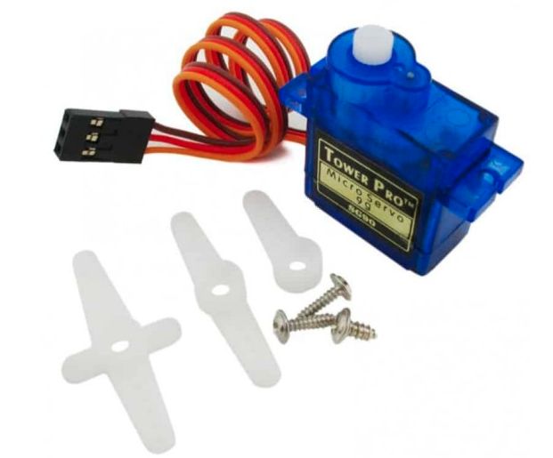
To keep things cheap and simple, SG90 and FS90R servo-motors are used, the latest is a continuous turn. One can find these nearly everywhere:
https://www.gotronic.fr/
https://www.cdiscount.com/
https://www.amazon.com/
https://www.banggood.com/fr/6PCS-SG90-Mini-Analog-Gear-Micro-Servo-9g-For-RC-Airplane-Helicopter-p-1078614.html?rmmds=search&cur_warehouse=CN
…
If delivery time isn’t a problem, the banggood solution cost 1.33€ per servo for 6 pieces (+delivery).
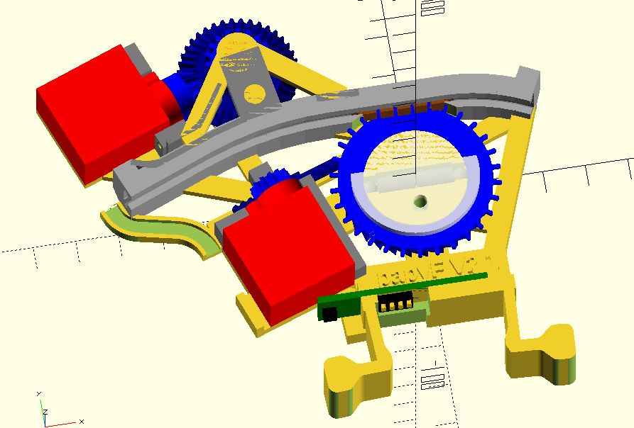
The tape pushing mechanism
The push the tape mechanism is made with the tape-servo, the tape-servo gear, the rack slider, the slots wheel, two cylinder magnets (D5mm x L8.5mm), two stainless steel balls (D4mm) and a place on the base body called block magnet.
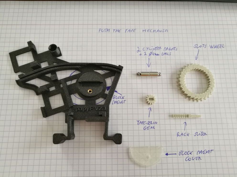
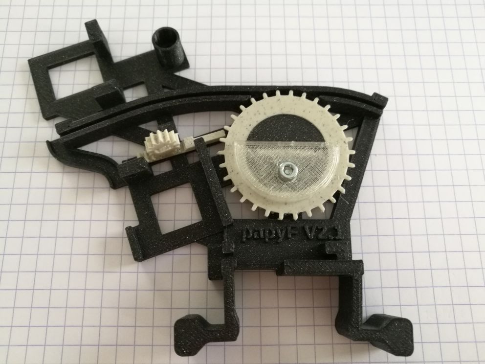
The elements are assembled in the base body:
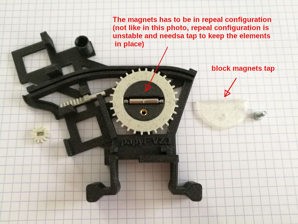
After, the block magnets tap is placed and secured with M3 screw. Doing this operation is touchy, first place the slots wheel, then place a ball and a magnet. Then place the second magnet in repeal configuration, this phase is tricky, there is a risk to place the stainless ball in orbit. Then place the second ball. During all the manipulations you can secure the elements with your finger. At the end, slide the block magnets tap gently in order to replace your finger with the tap. Finally, secure the tap with the M3 screw:
The film pulling mechanism
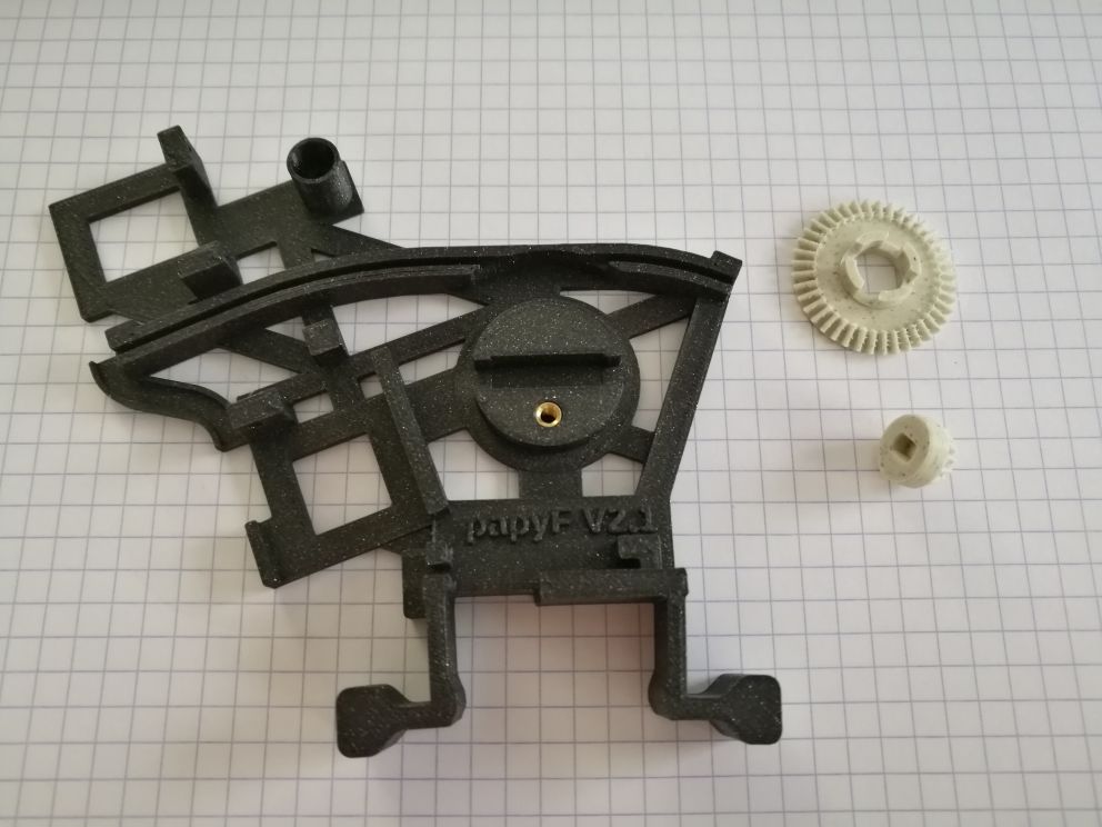
The photo hereafter shows the elements for this mechanism:
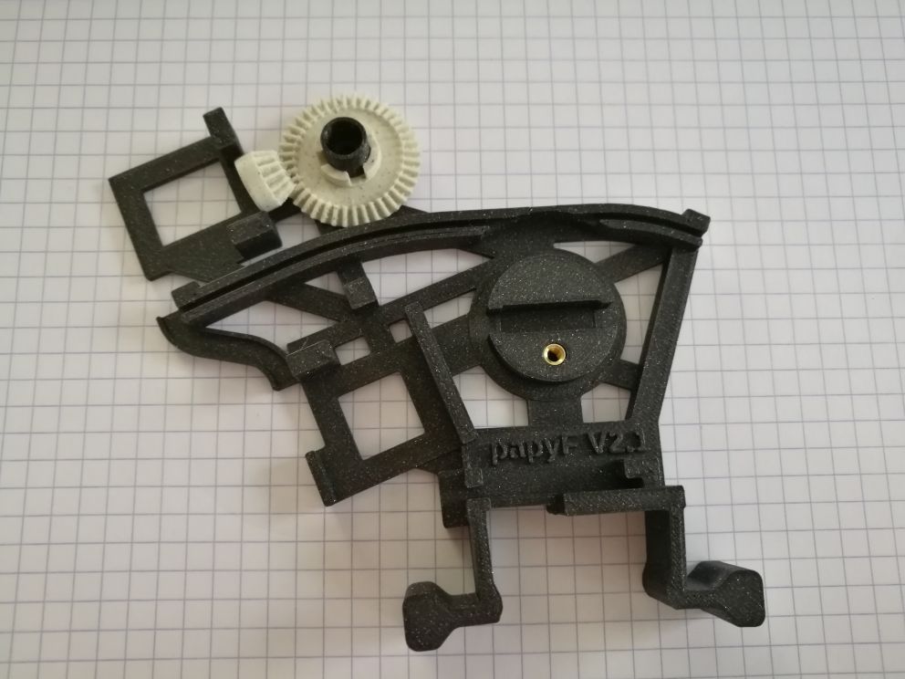
Assembled:
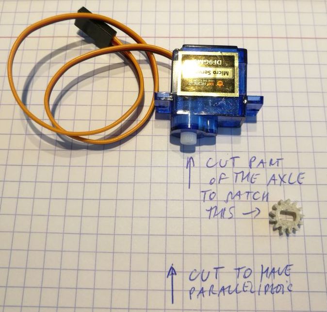
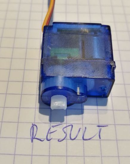
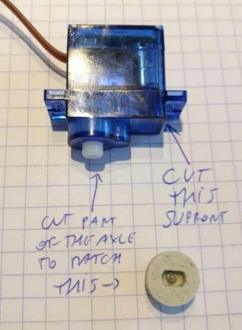
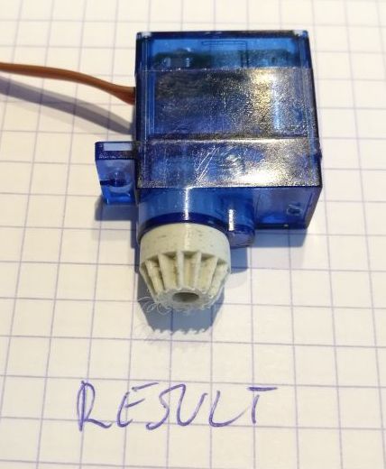
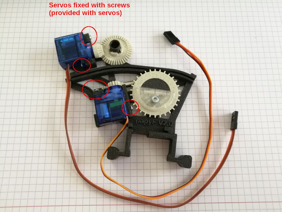
The servo-motors
The servo-motors need a little processing before use, the figures hereafter show the steps:
The base assembled
After all the processes described before, the feeder base is completed and looks like this:
The feeder base is the main component. A tap and two sprockets have to be added to have the complete feeder. These components have their size that depends on the tape width.
The tap and the two sprockets
Here after are shown the different taps and sprockets that correspond to the different tape width of 8/12/16/24mm:
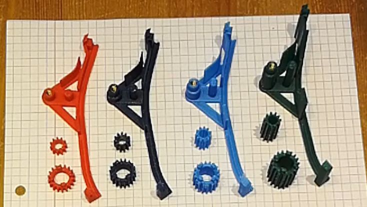
Assembling the taps is straightforward.
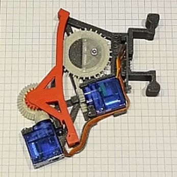
The feeder completed
Here after is a photo of a feeder with 8mm tap
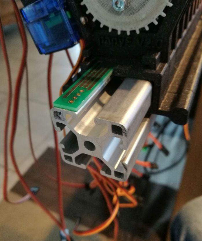
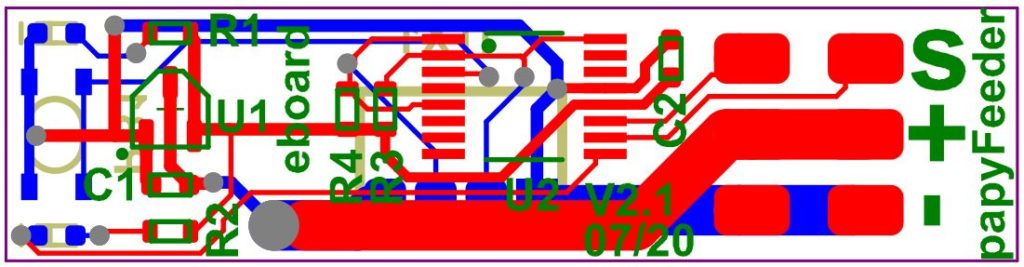
The feeder electronic board (V2.1)
Each feeder has an electronic board (eboard), that receive/transmit information over UART TTL bus and commands the two servomotors. The eboard has only a few components and one spring connectors. The schematic is given here after.
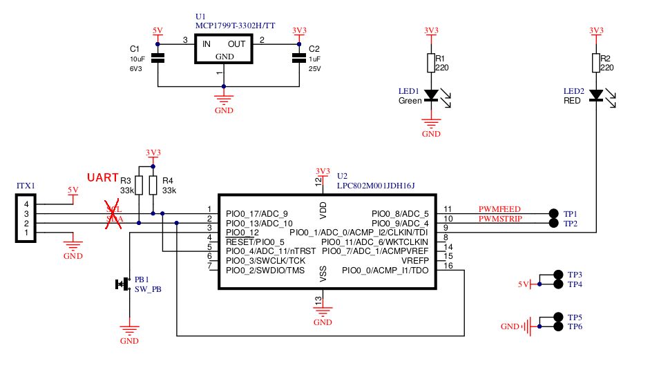
The board is a 2 layers 1.6mm FR4 HAL (43x10mm):
VIDEO
The mounting procedure is described here: https://youtu.be/8yfdeDc5FSU
A demo is available here: https://youtu.be/tyeOStteOyA
FILES
The files are available on github: https://github.com/papyDoctor/papyFeeder
The V2.1 snapshot (all the files) is here: FILES